

Case Study
Tips for Designing Plastic Parts
When designing with plastic, the goal is to achieve a technically accurate design that functions well and can be cost effectively manufactured. Following these basic tips will help in accomplishing these goals and accelerate the designing process.
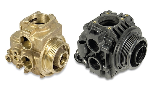
Today’s high performance plastics bring many benefits to the design table that others previously thought existed only with metal. These start with durability. The high performance plastics of today have been proven in many applications to be much stronger than metal over time. Every imaginable industry from plumbing, medical, and aerospace now have hundreds of applications where previously designed metal parts were converted to plastic.
Plastic molding experience is crucial
Designing products with molded plastic components and assemblies is becoming a more attractive option. New high performance plastics and innovative molding processes make this possible. Injection molded plastic parts offer an important combination of flexibility, toughness, and chemical resistance for cost effective, long-term performance in a range of applications. However, not every plastic part design can be efficiently injection molded. So working with an experienced molder with many years’ experience with high performance plastics and complex projects is important to a successful outcome. That way, you can be assured that your molded components and assemblies are both functional and within budget.
Knowing plastic materials and their correct selection
There are hundreds of plastic materials available, all with different performance characteristics. You need to understand what plastic will work best for your application. You should also understand the stresses that will affect the performance and the life of the part. Key questions to answer are: will part stress occur repeatedly or will it be a one-time occurrence? Will the stress in a moving plastic part experience a continual peak load and relaxation or will it be under constant load. What chemicals will come into contact with the part? Some plastics are very sensitive to specific chemicals whereas others are not. Both the plastic material supplier and an experienced molder will prove helpful in selecting the correct material for the application.
Importance of part uniform wall thickness
Uniform wall thickness is critical in part design for an injection molded part. Non-uniform wall thickness causes dimensional control problems, warpage, and other part integrity issues.
Material selection
Some materials can flow through thin wall sections and give the proper strength for its application. However, some materials do not move freely or contain fillers to improve the strength of the material chosen. These types of materials will require a thicker minimum thickness.
A good rule of thumb is to design all part cross-sections as thinly and uniformly as possible. The use of ribs is an effective way of achieving rigidity and strength while avoiding cross-sectional thickness.
Mechanical characteristics
These are needed for part integrity—what are the design requirements for the part? If this part is under constant load it may require a thicker wall section than a part that is not under any load.
In cases where it is impossible to avoid a thick cross-section, ribs may also help to minimize the distortion that can occur. Extremely complex shapes that must combine thick and thin cross-sections should be reviewed in advance so as to determine dimensional stability and tolerance changes that will occur during and after molding.
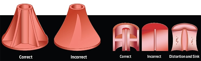
Material shrink also influences part integrity. Thermoplastic materials are heated at high temperatures in the barrel of the molding press and injected into the mold cavity. As the part cools in the mold, it shrinks. Thick cross-section areas cool at a substantially lower rate than thin cross-sections, and press cycle time is based on the cooling rate of the thickest cross-section. Therefore, only one relatively thick cross-section area of the part will increase the press cycle time thereby reducing the number of parts per hour and increasing the cost per part.
Also, the uneven rate of cooling of these thick and thin cross-sections is likely to result in distortion of the part after it has been removed from the mold. This distortion is often severe enough to prevent the part from meeting specifications. A thick cross-section is also likely to result in a depression on the surface called a sink mark, particularly if the cross-section is of varying widths.
Needed wall tapers for plastic molded components
Amount of taper or “draft” refers to the amount of taper of molded parts perpendicular to the parting line. The draft taper should be determined early in the plastic part design process. The need for part surface tapering facilitates ejection of the part from the mold, especially in high speed, high volume production applications.
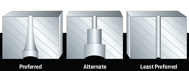
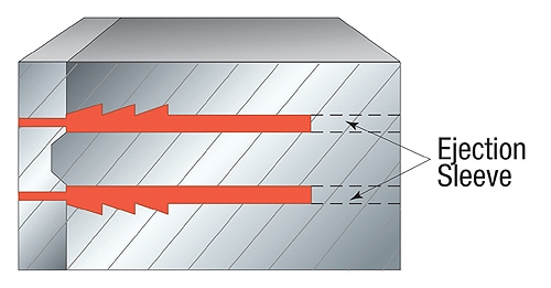
Long fragile cores tend to warp or break under continous use due to the heat and pressure of the operating environment.
Cost-saving hole design
A hole or inside diameter is created in a part by inserting a core pin in the cavity. Holes at a right angle to the mold parting line are relatively easy to produce since the core pin is parallel to the injection path. The normal shrinkage process, however, can cause the part to cling to the core as it cools in the mold. In order to facilitate ejection of the part from the mold, a draft should be incorporated along the length of the hole.
Holes that are parallel to the mold parting line call for the use of a sliding core that automatically retracts from the part as the mold opens. The use of sliding cores adds to the cost and complexity of tool design and construction. If a hole does pass completely through a part, or if the part contains holes on more than one side, the mold must be designed to hold the part on a specific side of the open mold to facilitate automatic parts unloading.
Long, fragile cores tend to warp or break under continuous use due to the heat and pressure of their operating environment. The size of thcorese core pin, and thus the diameter of the hole, should therefore be maximized whenever possible, particularly at the base, to ensure the stability of the pin. A useful rule of thumb to remember when designing part holes is the “2:1 rule”: The height of the hole should not be more than twice its diameter.
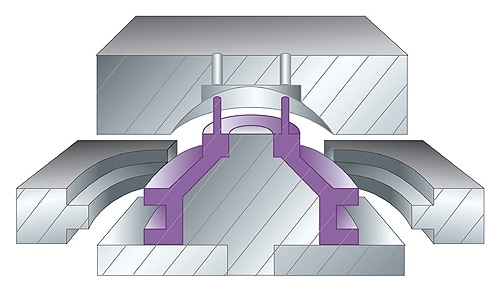
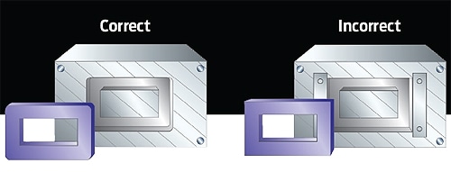
External part features and parting lines
As a rule of thumb, parts with external features need to be designed so that the part can span across a parting line. A witness line is required where two pieces of the mold come together. Therefore, if the surface finish is cosmetic this should be taken into account. If the part cannot span across a parting line, slides are needed to generate the feature. Also, direction of pull must be considered in the plane that will be pulled with the sliding steel.
Parts requiring features that need to be removed from the tool with sliding steel require a parting line.
Expect part warpage
Some warpage should be expected with any molded plastic part. The amount will vary with the type of thermoplastic material used, the gate location, and the wall section of the part. A consistent part wall section usually will have the least warpage and provide the best overall outcome.
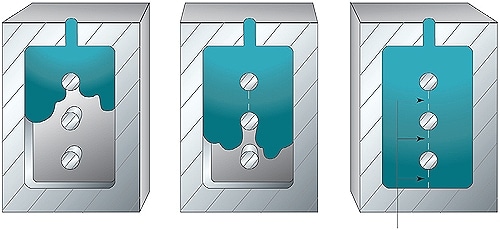
Eliminating knit lines
Knit lines are weak points where material flows together when a core pin blocks the normal path of the molten material as it enters the mold. This weak point occurs on the “back side” of the pin where the material flows together. These weak points can be eliminated by proper placement of the gate, or material entry point. It is very important to specify locations on the part where knit marks cannot be tolerated. This will eliminate potential problems in the mold design stage.
Achieving the best molded part corners
Since the mold is machined from steel, it is easier and less costly to machine a radius than a square corner. Whenever possible, parts should have round corners when viewed from the top of the mold. When viewed from the side, part edges should be square.
Note that due to the flow characteristics of the molten plastic during the molding process, square corners tend to be weaker than rounded corners. To ensure dimensional stability, a minimum radius of 0.010 in. (0.254 mm) is recommended.
Selecting a part surface finish
Molded plastic parts may be designed with a variety of surface finishes, from a high gloss to a rough texture. The choice of surface finish is usually based on cosmetic considerations. A glossy finish can enhance the appearance of a part while a textured surface may help to mask sink marks or parting lines.
Surface finish should be specified so it does not interfere with ejection of the part from the mold. The smoother the finish, the more easily the part is ejected from the mold. An extremely rough surface may hinder ejection from the mold. Rough finishes tend to function much like an outside dimension undercut thus preventing the part from slipping easily out of the mold.
When not otherwise specified, the surface finish standards of the Society of Plastic Engineers and the Society of Plastic Industries should be followed.
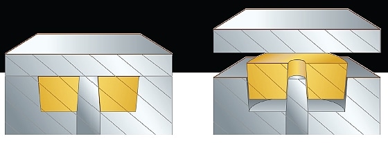
Molding in part inserts
Inserts made of steel, brass, and aluminum components are commonly inserted into plastic parts during or after the molding process. Having a knurled, ribbed, or abraded surface on the metal part helps to ensure a strong, permanent bond between metal and plastic so that the insert remains locked into the molded part. Design engineers who work with plastics can provide you with more information and assistance in designing your inserts.